New 8861 Design
First do the 8861 Sim
Some sim issues a small change to the Schotky diode means big changes to sim, both in results and sim speed. One Schotky choice didn't sim. Ended up with the RSX201VYM30 as I couldn't find a model for Charlie's choice.
First Try DC Vset (charlie_partB_02.asc)
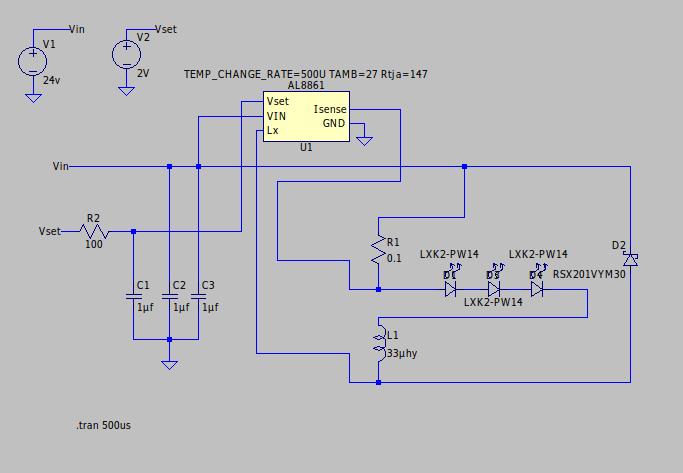
Appears to work. About 2 minutes to simulate. 2 volts on VSet. Sim as 900ma peak. Ripple current about 210ma. With 0.1 Rset should be about, $$I_{avg} = 2.0/2.5)\cdot(1.0)$$ $$I_{avg} = 800ma$$ and according to the sim is, $$I_{avg-sim} = 900 - (210/2)$$ $$I_{avg-sim} = 795ma$$
See image below.
Note: The 'Gear' method was used for the simulation.
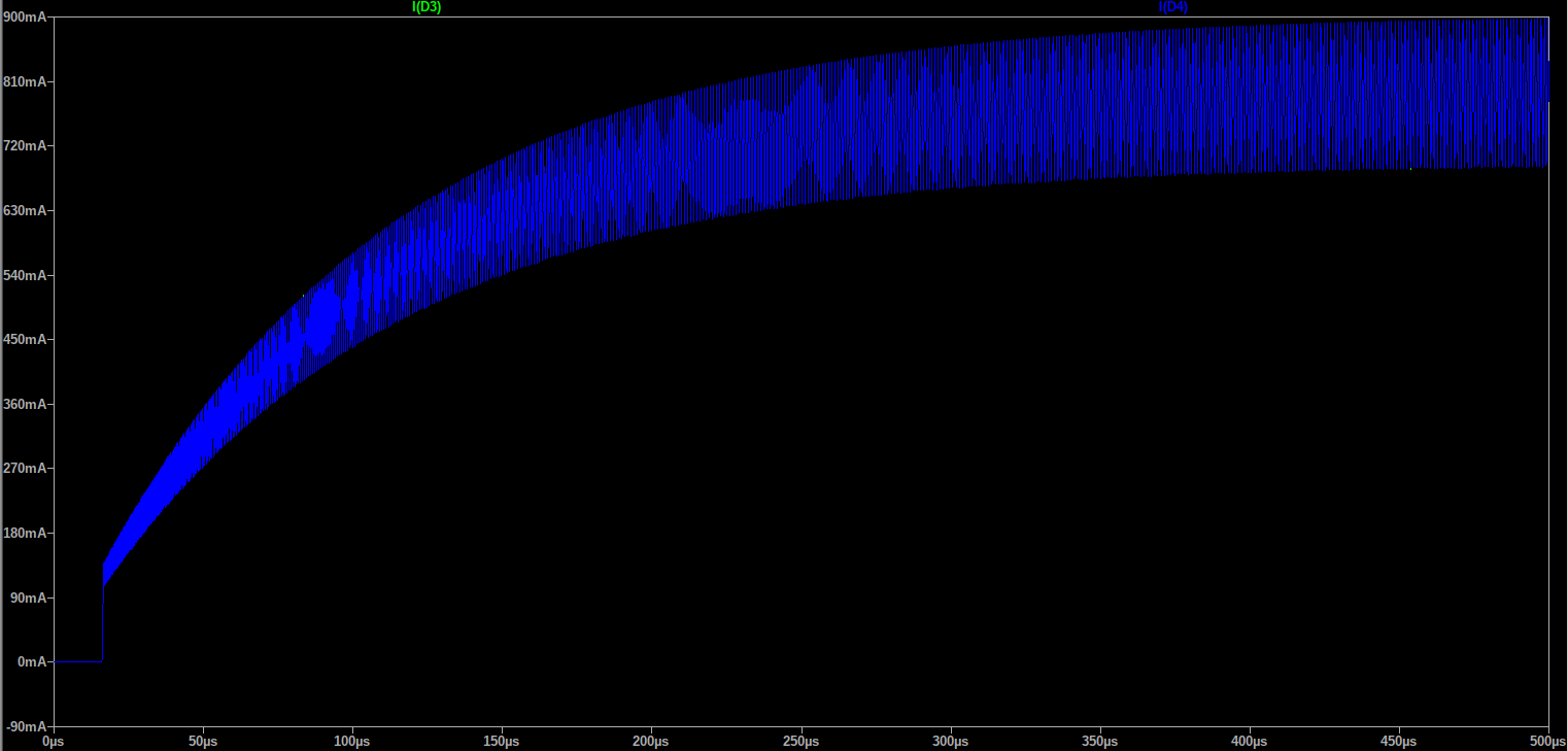
So it looks like the sim is working well.
Now try PWM Vset (charlie_partB_03.asc)

Looks good. Set PWM freq at 25Khz, duty cycle 50%. Result shows average current approximately 500ma. VSet shown in blue.
There is a sub nanosecond multi amp glitch occasionally. I'm guessing it's a model/simulator glitch.
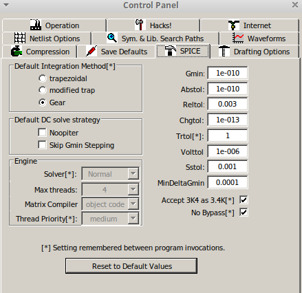
Had to change the LTSpice settings as shown for an RC front end to VSet to simulate.
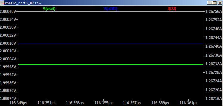
Tried to determine the input impedance of Vset by putting a 100 ohm in series the the 2V source and measuring the drop. Apparently this failed as the Vset pin is higher than the 2V input ..
2V source is green, the Vset pin is blue.Now Test the Analog Section
PWM Change
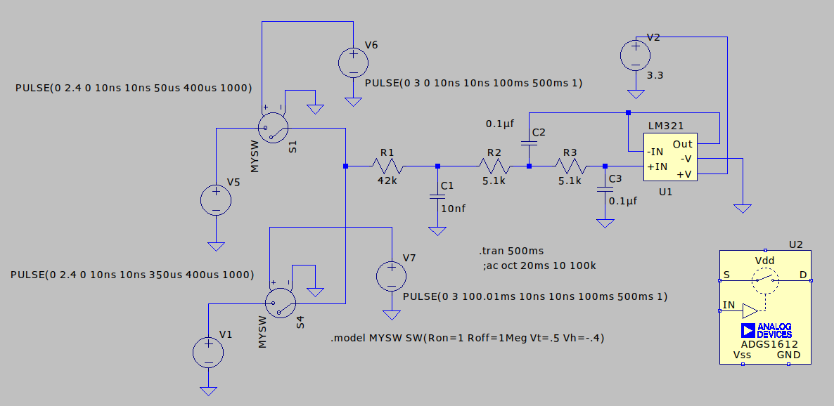
Will eventually be stitched in to the LED Driver sim.
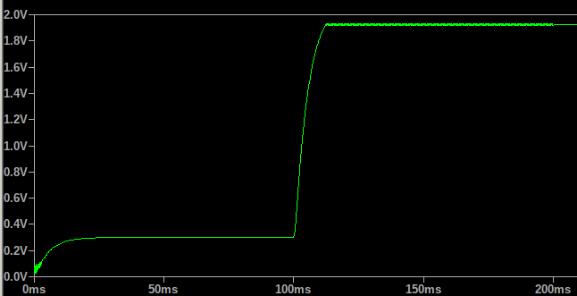
From 12% to 88%.
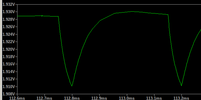
Ripple about 20mv at 88%.
Sims are working well with these slightly relaxed settings.
New Sims on 16 Core Machine
Sims are working well with these slightly relaxed settings.
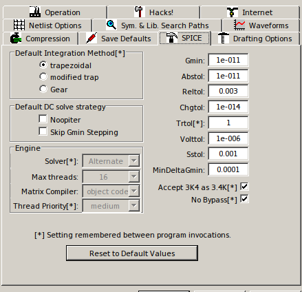
VSet DC with no C or R to Ground
(charlie_partB_05.asc)
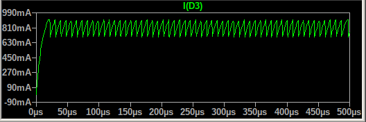
Now simulates well with no components on VSet pin. C1 is 1pf (see previous schematic), and no resistor to ground. Was previously problematic on slower computer and stricter settings. Not sure how well this is reflecting reality. Confidence 90%.
VSet PWM with no C or R to Ground
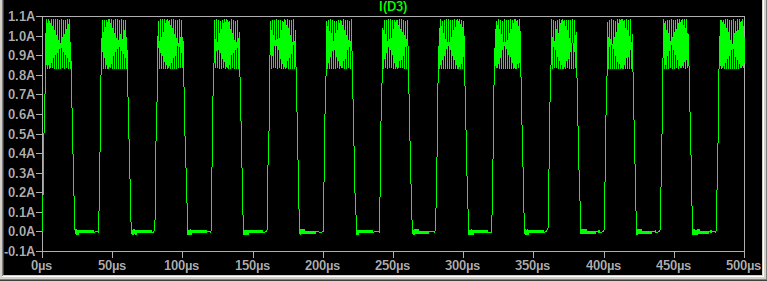
25Khz PWM, 2.4V peak VSet, 50% duty cycle. Current looks quite accurate.
There is still a concern that some capacitance to ground provides a soft startup (a.k.a. Flashing; our canonical problem). Charlie's breadboard does not exhibit this nor does the sim but it's still a concern.
Combine Analog Filter and LED Driver
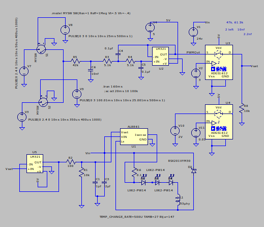
Here's the combined schematic. It will switch between VSet/DC and VSet/PWM. The PWM phase is divided into two parts; 20% PWM and 80% PWM to determine response time of the filter.
The simulation is very slow and showed poor results (for as long as it ran).
Part of the problem is the LM321.
Poor Slew Rate of Voltage Follower
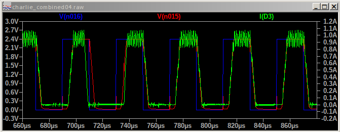
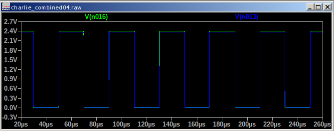
The LM321 voltage follower isn't.
It's slew rate is 0.4V / us
Translated .. 6us rise and fall times out of a 40us period.
See image above.
This is a better follower .. but it's not cheap, several dollars.
We need to find one with 3V/us slew rate to give better accuracy.
I looked for a discrete solution (cheap) but it has a 50mv offset. I verified this with Herman. It would track temperature but it would have a fixed offset. Are we back to Dave adding another table?
Six LEDs Switcher Sim
Fixed Voltage VSet
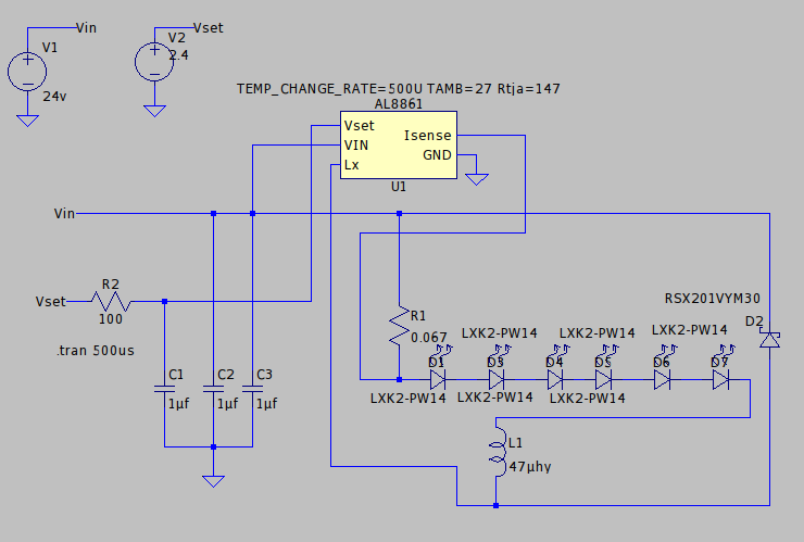
Per your suggestion .. 47uhy, 6 LEDs, 24V.
Sim Result ..

- Red is the instantaneous voltage drop across the 6 LEDs
- Green is the LED current
Note the limit is about 1.2A
Perhaps the LEDs you are using have a different (lower?) voltage drop.
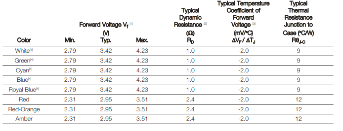
Here's a datasheet for the simulated LEDs.
PWM VSet
Setup
- Same schematic as above but fixed VSet
- Fixed Voltage (1V) for VSet
- 25Khz PWM
- 50% duty cycle
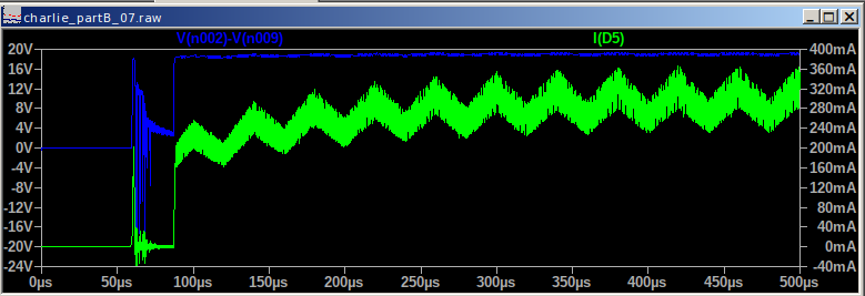
Sim Result
Junk in the front?
- Blue is instantaneous Vf of the 6 LEDs
- Green is the LED current.
Vf a little over 18V.
Average current about 300ma
# Is 300ma correct?
Iavg = (1/2.5)*1.5*0.5
print ("I average ->", Iavg)
Looks good.